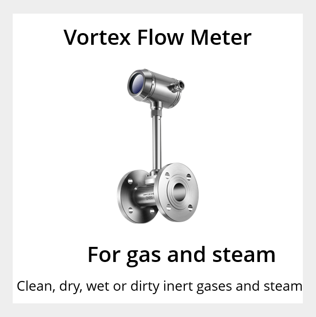

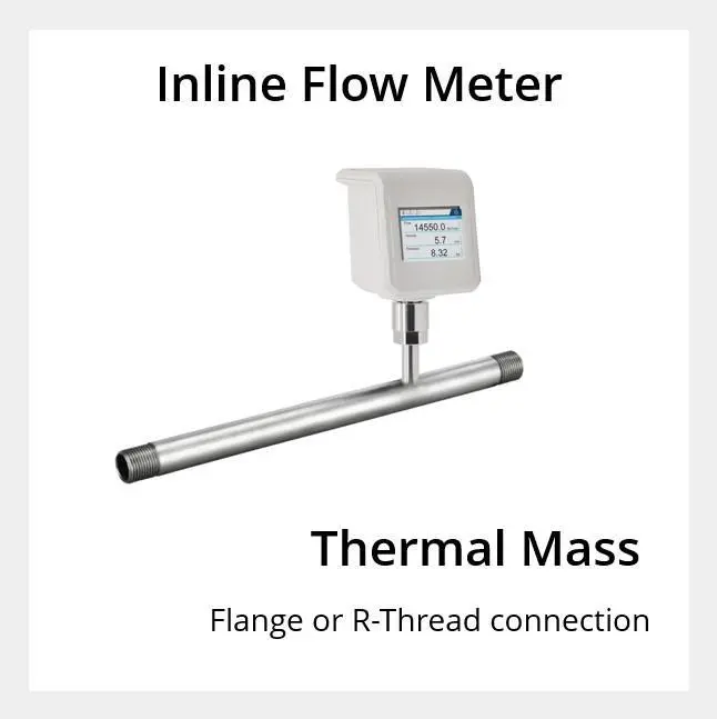
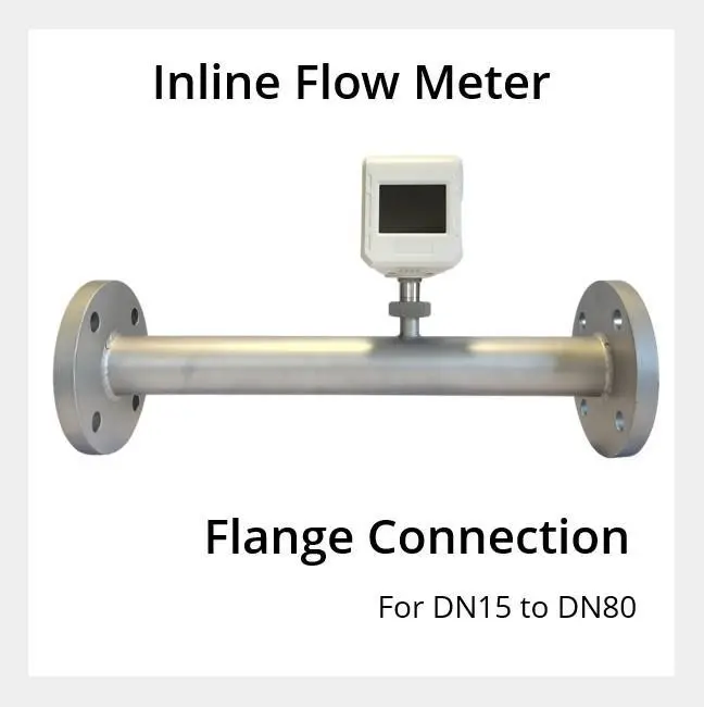
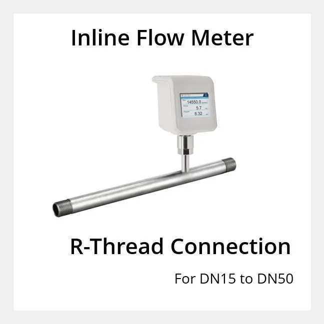
Inline type, thermal mass flow meter. Flange (DIN) or R-Thread pipe connection. Suitable for pipe sections from DN15 to DN80.
Flow Range
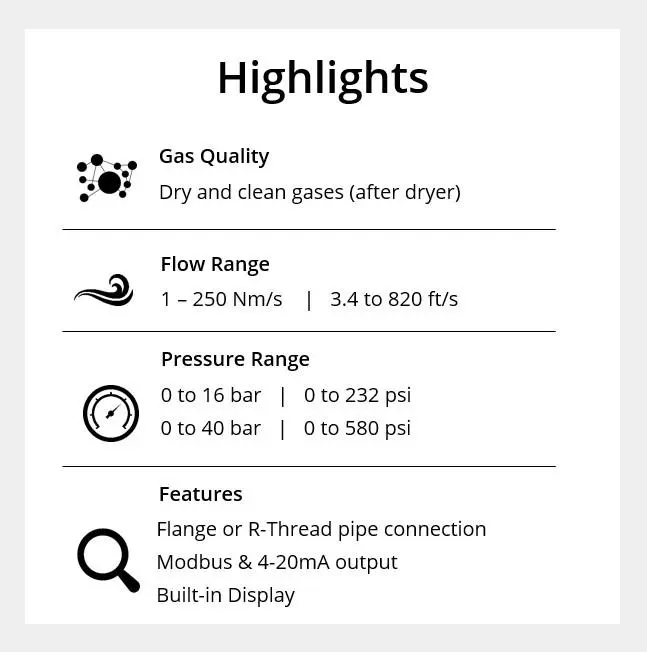
0.1 to 250 Nm/sec (0.3 to 820 ft/sec)
Gas Pressure Range
up to 40 bar (600 psi)
Gas Quality
Clean and dry compressed air and inert gases
Pipe Sizes
DN15 to DN80
Pipe Connection
Flange or R-Thread
Accuracy
Flow: ±1.5% reading, ±0.3% full scale
(high accuracy ±1% reading, ±0.3% full scale available on request)
Output
Modbus (RS485) and 4-20mA
Measure
Flow, Mass Flow, Consumption and Temperature
Power Requirement
18 to 30VDC / 5W@24VDC
Bi-directional
No
Measurement Principal
Mass Flow
Application
Manufacturing and industrial use
Temporary or permanent installation
Accessories
The transparent Flow Meter Enclosure will protect the flow meter head from liquids and other damage. Extra M12 connectors and data cables are available on the Accessories page.
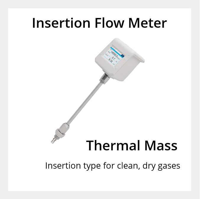
Thermal mass flow meters are perfectly suited for measuring clean, dry compressed air and inert gases, where accuracy on smaller pipe sizing is important. We offers two types of thermal mass flow meters – inline (or in-line) flow meter and insertion flow meter.
Inline Flow Meters
- Inline flow sensors include a section of pipe as part of the flow meter. Threaded pipe sections are available from DN15 to DN50. Flange pipe sections are available from DN15 to DN80.
- Inline flow meters are best suited to permanent installations as you will need to cut out a section of pipe to install the flow meter. You will also need to turn off compressed air while you install the inline flow meter.
Insertion flow meters
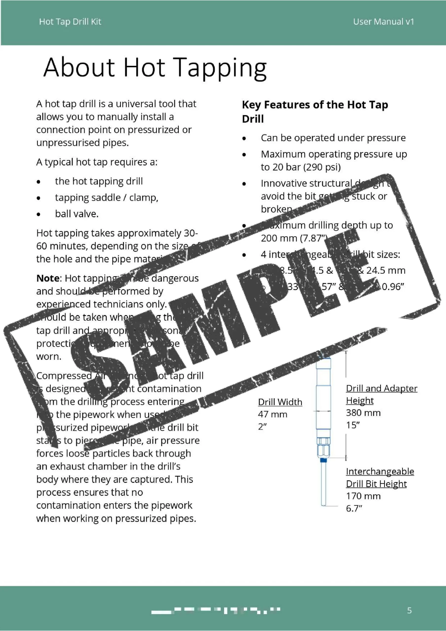
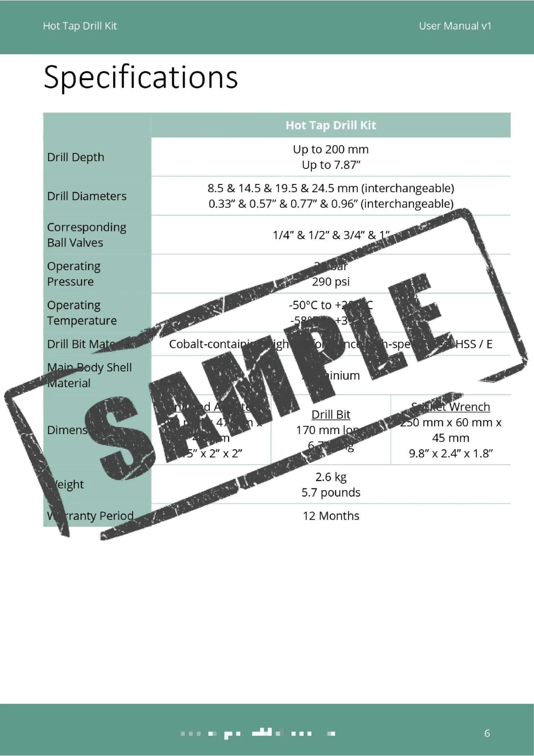
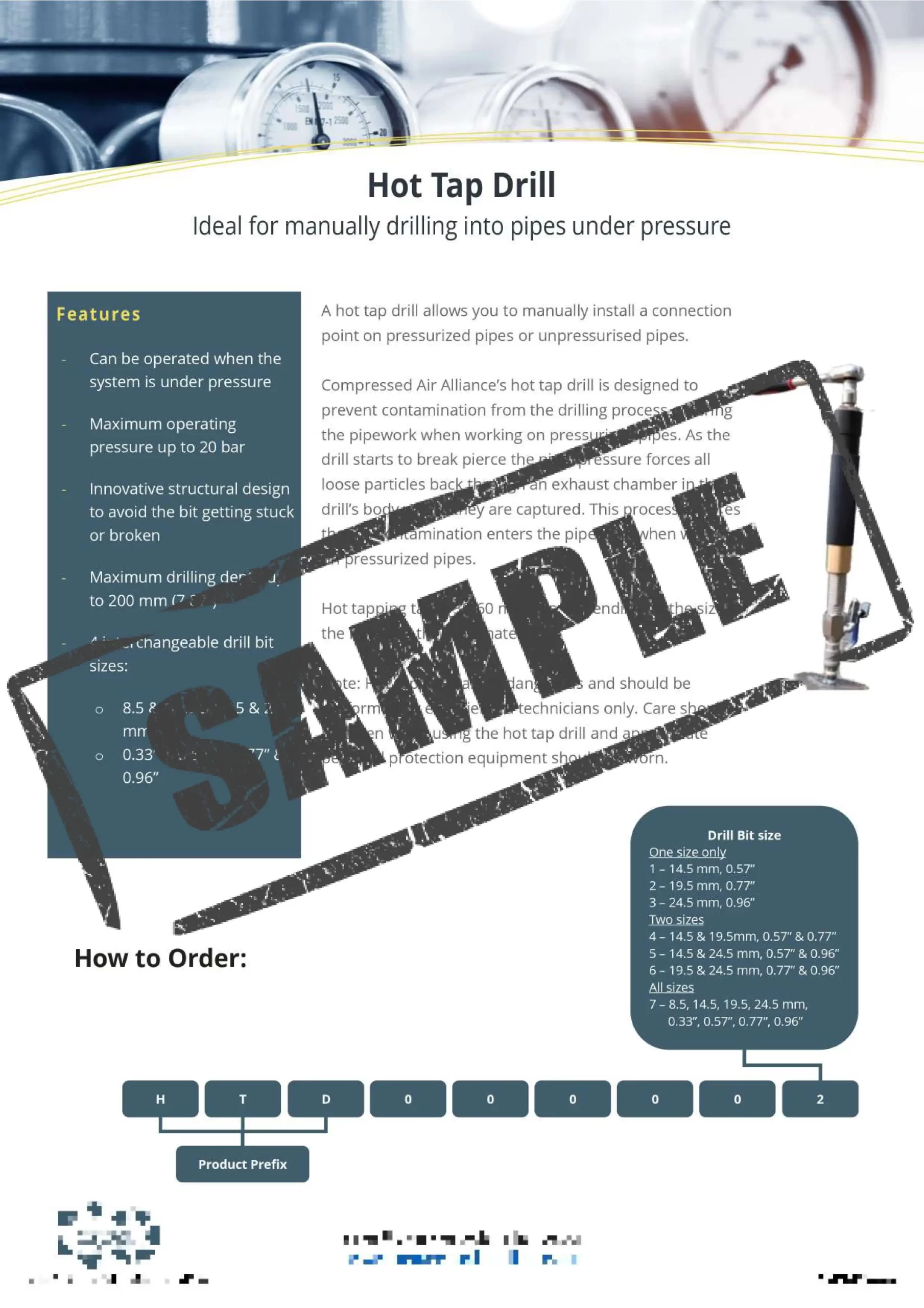
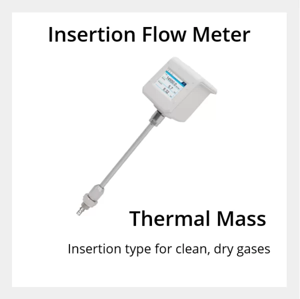
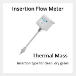
- Insertion flow sensors are inserted into the pipe through a valve. They can be inserted under pressure so you don’t need to turn off your compressed air system during installation.
- Insertion flow meters are best used for permanent and temporary installations.
- For information on the Insertion flow meter, refer to the Thermal Mass Flow Meter page.
Both of thermal mass flow meters (inline and insertion style) have a streamlined sensor tip which ensures minimal impact on gas flow while maintaining accuracy over a wide flow range.
Features of Inline Flow Meters
- Inline type sensor
- Thermal mass technology, independent of temperature and pressure change
- Measurement range: 0.1 to 250 Nm/s (820 ft/s)
- Integrated temperature sensor
- Accuracy of ±1.5% reading, ±0.3% full scale (high accuracy ±1% available on request)
- Modbus RTU and 4 to 20 mA + Pulse outputs
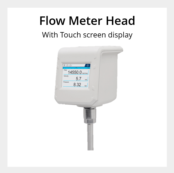
- 2.8″ ultra-wide viewing angle LCD touch screen
- Data logging with up to 10,000,000 recording points
- Suitable for pipes from DN15 – DN80 provided minimum velocity is maintained
- Measures standard flow, mass flow, consumption and temperature
- 12 month warranty
- Ultra-wide 1:2500 turndown ratio
- Full digital signal processing for higher precision and better stability
- Integrated gas temperature measurement
- No moving parts, low pressure drop
- Full electrical isolation to filter out disturbances
- Stable signals
- Vibration resistant
Inline Flow Meter comes with:
- M12 connector (data cable optional)
- Calibration certificate
- User Manual
- 12 month warranty
Inline Flow Meter Options
- Pressure: 1.6 MPa (16 bar) or 4.0 MPa (40 bar)
- Pipe Connection: Flange (DIN) or R-Thread
- Pipe Section: DN15, DN20, DN25, DN32, DN40, DN50, DN65 or DN80
- Gas Types: Air, Argon, Carbon Dioxide, Helium, Hydrogen, Natural Gas, Nitrogen, Nitrous Oxide, Oxygen
Important
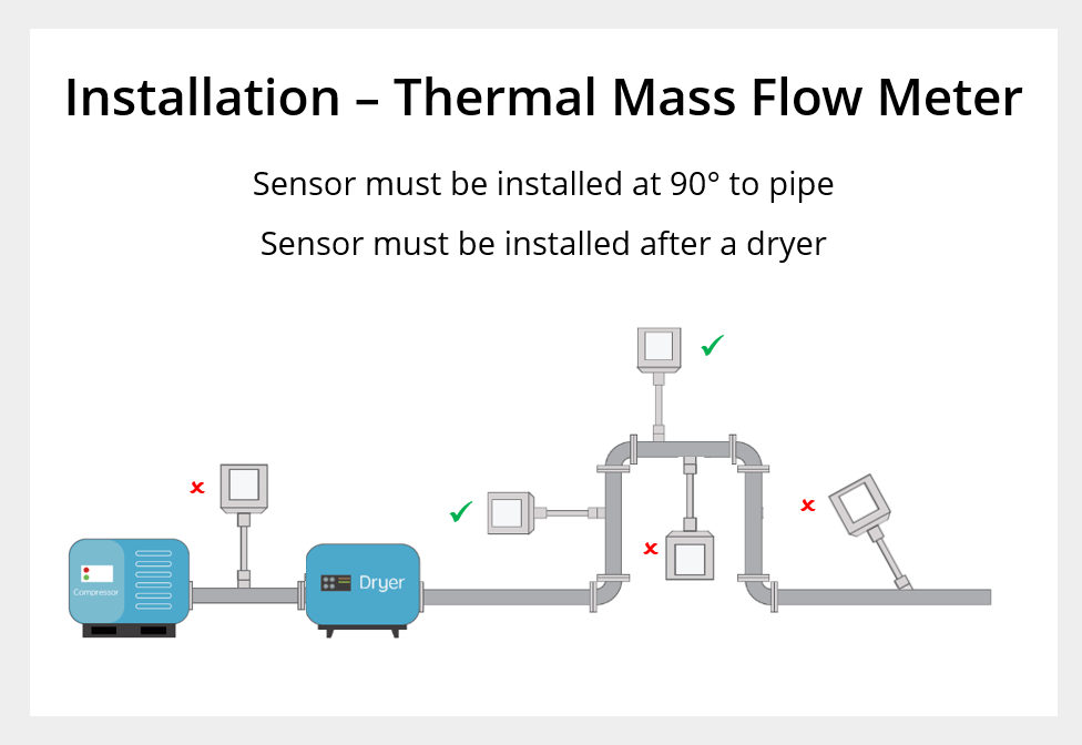
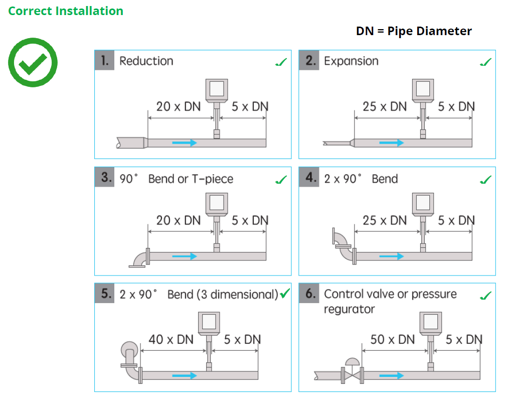
The sensor must be installed (i) in dry gas, (ii) at 90° to the pipe and (iii) away from bends, edges, seams, changes in pipe size and other obstructions,
Incorrect wiring or installation can give false readings, damage the sensor and void the warranty. If you aren’t sure how to install or wire the sensor, please contact us. Full installation and wiring instructions are available in the User Manual.
Warranty & Calibration
12 month warranty
Calibration is recommended every 2 years (provided the sensor is not exposed to relative humidity above 85%).
Annual calibration is required if the sensor is exposed to relative humidity above 85%.
Accessories
Accessories such as mechanical and electrical fittings are available.
Other Information
Part Numbers for 16 bar flow sensor, R-Thread Connection: FLF110001, FLF120001, FLF130001, FLF140001, FLF150001, FLF160001, FLF110011, FLF120011, FLF130011, FLF140011, FLF150011, FLF160011, FLF111001, FLF121001, FLF131001, FLF141001, FLF151001, FLF161001, FLF111011, FLF121011, FLF131011, FLF141011, FLF151011, FLF161011
Part Numbers for 40 bar flow sensor, R-Thread Connection: FLF210001, FLF220001, FLF230001, FLF240001, FLF250001, FLF260001, FLF210011, FLF220011, FLF230011, FLF240011, FLF250011, FLF260011, FLF211001, FLF221001, FLF231001, FLF241001, FLF251001, FLF261001, FLF211011, FLF221011, FLF231011, FLF241011, FLF251011, FLF261011
| Weight | N/A |
|---|---|
| Dimensions | N/A |
Specificiations
General
Technology |
Thermal mass, Inline design |
Gases |
Air, Argon, Carbon Dioxide, Helium, Hydrogen, Natural Gas, Nitrogen, Nitrous Oxide, Oxygen |
Gas Quality |
Clean and dry gases |
Accuracy |
Flow: ±(1.5% reading + 0.3% full scale)
Note: the accuracy of the sensor is affected by on-site conditions. Contaminants such as oil, high humidity or other impurities can affect the calibration and accuracy of the sensor. |
Minimum Gas Flow Required |
|
Measurement Ranges
Flow Measurement Range |
|
Pressure Measurement Range |
|
Gas Temperature Measurement Range |
|
Output
Outputs |
|
Modbus Output Signals |
|
Analogue Output Signals |
One measurement only |
Power Supply
Power |
18 to 30VDC / 5W@24VDC |
Electrical Connection |
2 x 5 pin M12, female |
EMC |
According to IEC 61326-1 |
Data Logger and Display
Data Logger |
10,000,000 samples
> 20 samples / second |
Display |
2.8” LCD with touch panel |
Other Information
Pipe Sizes |
DN15 to DN80 |
Process Connection |
R thread (ISO-7-1)
Flange (DIN), PN16 and PN40) |
Ambient Temperature Range |
|
Installation Type |
Permanent installation |
Calibration Frequency |
|
Warranty Period |
12 months |